Automatisierung des Labors/en: Unterschied zwischen den Versionen
K (translated halfway) |
(translation complete, looking for missing word, see discussion) |
||
| Zeile 4: | Zeile 4: | ||
So far the automation has been used for the following tasks: | So far the automation has been used for the following tasks: | ||
When you leave the Labor in the evening (or the early morning...), a simple twist of our main power button engages the shutdown procedure, which will turn off the music, the audio hardware, the light, all computers and some other non-essential appliances. One can control the lights and the music for all rooms using a [[Funkfernbedienung/en remote control]] or the [https://roulette.das-labor.org/weblabctrl/ website]. | When you leave the Labor in the evening (or the early morning...), a simple twist of our main power button engages the shutdown procedure, which will turn off the music, the audio hardware, the light, all computers and some other non-essential appliances. One can control the lights and the music for all rooms using a [[Funkfernbedienung/en|remote control]] or the [https://roulette.das-labor.org/weblabctrl/ website]. | ||
Sounds practical, eh? | Sounds practical, eh? | ||
| Zeile 22: | Zeile 22: | ||
| 0x24 || BORG || Long [[Blinken Borgs/en|scrolltext borg]] | | 0x24 || BORG || Long [[Blinken Borgs/en|scrolltext borg]] | ||
|- | |- | ||
| 0x31 || MOODBAR || | | 0x31 || MOODBAR || Fluorescent lamp dimmer bar (PC power supply case) | ||
|- | |- | ||
| 0x35 || LAMPE || SpotControl (Metal case) | | 0x35 || LAMPE || SpotControl (Metal case) | ||
| Zeile 44: | Zeile 44: | ||
=== 2.9.2005 === | === 2.9.2005 === | ||
For now we can already talk to the CAN controllers via the [[Labor Micro Board/en]] to send and receive CAN packets. We also have written a small software for Atmel | For now we can already talk to the CAN controllers via the [[Labor Micro Board/en|Labor Micro Board]] to send and receive CAN packets. We also have written a small software for Atmel micro controllers which turns them into a CAN<->RS232 gateway. For the PC side, we've developed a client software, giving the computer the ability to send and receive CAN packets. It is even possible to tunnel the packets through Ethernet. | ||
| Zeile 50: | Zeile 50: | ||
[[Bild:CAN-GW-Roulette.jpg|150px|left]] | [[Bild:CAN-GW-Roulette.jpg|150px|left]] | ||
We've built a CAN RS232 gateway into a 19" rack-case. | We've built a CAN RS232 gateway into a 19" rack-case which I scavenged from junk. Received CAN packets are tunneled through RS232 so that a host software can receive and unpack them. The case contains a power supply for our 13V bus power supply (has been lowered from 24V) and a bunch of LEDs to signal various operating conditions sometime. Furthermore there's a main board with an ATmega8 at its core. The board also houses the components for the CAN bus and a MAX232 for the serial side. Not to forget, there are shift registers and 16 drivers for the LEDs in the rest of the case (it has already been there...). | ||
<br /><br /><br /><br /> | |||
== Dimmer for Spotlights == | |||
== Dimmer | |||
[[Bild:LAPDimmer.jpg|150px|left]] | [[Bild:LAPDimmer.jpg|150px|left]] | ||
[[Bild:LAPSpots.jpg|150px|right]] | [[Bild:LAPSpots.jpg|150px|right]] | ||
I've built a dimmer for our spotlights into a small metal case. | |||
The spots are 30W/6V PAR34 spots. The case contains not only the power electronics but also the control. The control functions are being served by a (much too small...) AT90S2313. It is accompanied by the ICs for the CAN bus and a relais, that can cut off the spots from mains supply. | |||
<br /><br /><br /><br /> | <br /><br /><br /><br /> | ||
== | == Scrolltext Borg == | ||
<div>[[Bild:LS-Borg.jpg|150px|left]] | <div>[[Bild:LS-Borg.jpg|150px|left]] | ||
The scrolltext-[[Blinken Borgs/en|borg]] at the bar shall be abused for joystick-based control and to show various operating modes of the Labor. | |||
</div> | </div> | ||
<br /><br /><br /><br /><br /><br /> | <br /><br /><br /><br /><br /><br /> | ||
| Zeile 75: | Zeile 72: | ||
<div>[[Bild:Theke2.jpg|150px|left]] | <div>[[Bild:Theke2.jpg|150px|left]] | ||
The bar has an integrated 3-channel [[Moodbar/en|fluorescent lamp dimmer]] -- it mixes arbitrary and wonderfull colors. | |||
</div> | </div> | ||
<br /><br /><br /><br /><br /> | <br /><br /><br /><br /><br /> | ||
== | == Technical Stuff == | ||
=== | === Pinout of new CAN bus plug === | ||
We're using one of those connectors like the ones famous from IDE cables, the ones with the plastic fringe. | |||
Top view pin header: View from the plugging-side on the pins | |||
9 7 5 3 1 | 9 7 5 3 1 | ||
Version vom 15. Mai 2009, 00:39 Uhr
We have started to automate the Labor using a CAN bus. The LAP protocol has been developed to support our goal.
The basic idea is that we liked to have an automatic and convenient controller for all our lamps, the music and other fancy stuff. We had thought about providing a means of interaction to the system using common wall mounted light switches and remote controls as well as via a website in our intranet.
So far the automation has been used for the following tasks: When you leave the Labor in the evening (or the early morning...), a simple twist of our main power button engages the shutdown procedure, which will turn off the music, the audio hardware, the light, all computers and some other non-essential appliances. One can control the lights and the music for all rooms using a remote control or the website.
Sounds practical, eh?
We have planned to extend the automation to do some other tasks as well, for example to separately control the power outlets located in the Labor.
Status
Assigned LAP Addresses
| Address | Device | Description |
|---|---|---|
| 0x00 | CAN-GW | at Roulette |
| 0x01 | The Might (aka The Switch) | |
| 0x24 | BORG | Long scrolltext borg |
| 0x31 | MOODBAR | Fluorescent lamp dimmer bar (PC power supply case) |
| 0x35 | LAMPE | SpotControl (Metal case) |
| 0x3d | BORG-3D | Martin's 8x8x8 Blinken-Borg |
| 0xA1 | dr4go's Moodlight | |
| 0x42 | BORG | Andre's small 16x16 Blinkenlights |
| 0x43 | Dario's LaBORGjacket | |
| 0x53 | Gate opener | |
| 0x54 | Chuck/en | |
| 0xF? | BROADCAST | Special broadcast addresses |
| 0xFF | BROADCAST | All LAP Devices |
2.9.2005
For now we can already talk to the CAN controllers via the Labor Micro Board to send and receive CAN packets. We also have written a small software for Atmel micro controllers which turns them into a CAN<->RS232 gateway. For the PC side, we've developed a client software, giving the computer the ability to send and receive CAN packets. It is even possible to tunnel the packets through Ethernet.
CAN <-> RS232 Gateway
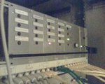
We've built a CAN RS232 gateway into a 19" rack-case which I scavenged from junk. Received CAN packets are tunneled through RS232 so that a host software can receive and unpack them. The case contains a power supply for our 13V bus power supply (has been lowered from 24V) and a bunch of LEDs to signal various operating conditions sometime. Furthermore there's a main board with an ATmega8 at its core. The board also houses the components for the CAN bus and a MAX232 for the serial side. Not to forget, there are shift registers and 16 drivers for the LEDs in the rest of the case (it has already been there...).
Dimmer for Spotlights
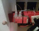
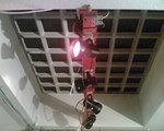
I've built a dimmer for our spotlights into a small metal case.
The spots are 30W/6V PAR34 spots. The case contains not only the power electronics but also the control. The control functions are being served by a (much too small...) AT90S2313. It is accompanied by the ICs for the CAN bus and a relais, that can cut off the spots from mains supply.
Scrolltext Borg
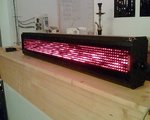
The scrolltext-borg at the bar shall be abused for joystick-based control and to show various operating modes of the Labor.
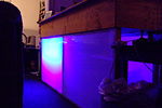
Moodbar
The bar has an integrated 3-channel fluorescent lamp dimmer -- it mixes arbitrary and wonderfull colors.
Technical Stuff
Pinout of new CAN bus plug
We're using one of those connectors like the ones famous from IDE cables, the ones with the plastic fringe.
Top view pin header: View from the plugging-side on the pins
   9   7   5    3   1
+--------[   ]---------+
| 15V 15V GND CANH GND |
| 15V 15V GND CANL GND |
+----------------------+
   10  8   6    4   2
