Locodoco/Loco Decoder: Unterschied zwischen den Versionen
Soeren (Diskussion | Beiträge) K (+ navi) |
Soeren (Diskussion | Beiträge) KKeine Bearbeitungszusammenfassung |
||
| Zeile 7: | Zeile 7: | ||
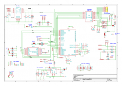
[[Datei:Locodoco_decoder_big.png|thumb|right|250px|Schematic of the Loco decoder Version 2]] | [[Datei:Locodoco_decoder_big.png|thumb|right|250px|Schematic of the Loco decoder Version 2]] | ||
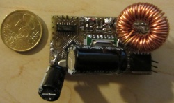
[[Datei:Locodoco-decoder-v2.jpg|thumb|right|250px|First prototype]] | [[Datei:Locodoco-decoder-v2.jpg|thumb|right|250px|First prototype]] | ||
[[Datei:Locodoco v2 schoema.jpg|thumb|right|250px|Prototype in LGB Schöma disel loco]] | |||
'''List of features''' | '''List of features''' | ||
* measurement of rail voltage | * measurement of rail voltage | ||
Aktuelle Version vom 5. Juni 2012, 14:10 Uhr
List of features
- measurement of rail voltage
- measurement of generator voltage (motor speed/load regulation)
- DCC support
- connector for IR transceiver
- seperate out/inletlets for each, motor-driver and logic power supply (GoldCaps)
- 4 GPIO Pins
- Processor: One out of Atmega8, Atmega168 and friends (all pin compatible devices)
- 5V/3A Power supply
- 4A motor Driver
- max. 4A total current (for the sum of motor- and 5V power)
- Switching outputs: (5x500mA + 1x1A) or (3x500mA + 1x1A + 2x8A) with seperate GND
- 2-stage load regulation (0-6V and 0-24V), 1024b percision
- 2 GPIOs (i.e. for Servos or SUSI interface)
The circuit is designed to be as flexible as possible and highly configurable by the user. Many components are optional and don't have to be present on the board to provide basic functionality. The LM2576 power regulator provides up to 3A and 5V for the logic and peripherals - enough power to drive several servos and a smoke generator.
Motor velocity measurement[Bearbeiten | Quelltext bearbeiten]
Motor velocity, or the generator voltage is measured accross both connectors of the motor. The resistor network of the motor measurement circuit is designed to forward 1/6 th of the generator voltage to the ADC of the AVR when the "sense_dec" resistor is not connected and 1/24th of the voltage when the resistor is connected to GND. Since the ADC of an Atmega328P has a reference voltage of ~1V at max., this schematic allows for sampling generator voltages up to 6V at a resolution of 1024bits - thus provides a very accurate reference (~6mV per Step) and very percise driving behaviour at low speeds. For voltages above 6V, the "sense_dec" resistor must be pulled to GND to assure that the reference volage is still within the measurable range of the ADC. When pulled to GND, the entire resistor network divides the generator voltage by (approx.) 24. With the division factor 24, the ADC measurement equals ~23mV per step.
Load regulation[Bearbeiten | Quelltext bearbeiten]
A common feature among digital model railroad systems is load regulation and measurement of the actual speed of the motor. When performing scripted actions like (de)coupling cars on a certain point of the layout, it is essential to know the actual speed of the loco. I've done some experimenting with different circuits and documented the results in a small video.
Locodoco Project | Position tracking system | Loco decoder | Webinterface


