Locodoco: Unterschied zwischen den Versionen
Soeren (Diskussion | Beiträge) |
D2ns (Diskussion | Beiträge) Keine Bearbeitungszusammenfassung |
||
| (14 dazwischenliegende Versionen von 2 Benutzern werden nicht angezeigt) | |||
| Zeile 1: | Zeile 1: | ||
{{ProjektInfoBox | {{ProjektInfoBox | ||
|name | |name=locodoco | ||
|status | |status=experimental | ||
|image | |image=Locodoco-train1.jpeg | ||
|description = An open source model railroad control infrastructure. | |description=An open source model railroad control infrastructure. | ||
| | |username=Soeren | ||
| | |author=Soeren | ||
|platform=AVR Microcontrollers | |||
|license=GPL | |||
|platform | |download=[https://github.com/soern/locodoco/ Github]<strike>[[http://www.das-labor.org/trac/browser/locodoco Trac]] [[https://www.das-labor.org/svn/locodoco SVN]]</strike> | ||
|license | |tags=Bewegung und Mechanik, | ||
|download | |update= | ||
}} __NOTOC__ | }} | ||
__NOTOC__ | |||
{| style="border-color:#EEEEEE;border-style:solid;padding:8px;float:left;margin-right:10px;margin-bottom:10px;margin-top:2em;" | |||
|- style="vertical-align:top;" | |||
| | |||
== Components & Building Blocks == | |||
{| | |||
| | |||
{{Imagemap|Locodoco-decoder-v2.jpg|Locodoco/Loco_Decoder|width=140px|mod=center|alt=Loco Decoder V2|caption=Loco Decoder|description=none}} | |||
» [[Locodoco/Loco_Decoder|Loco Decoder]] | |||
| | |||
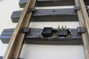
{{Imagemap|Locodoco_Irsender_v1_top.jpg|Locodoco/Position_Tracking|width=140px|mod=center|alt=Position tracking node built into LGB track|caption=Position tracking|description=none}} | |||
» [[Locodoco/Position_Tracking|Position Tracking]] | |||
|- | |||
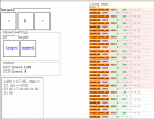
|{{Imagemap|Ldc_webif.png|Locodoco/Webinterface|width=140px|mod=center|alt=Webinterface for the Locodoco project|caption=Webinterface|description=none}} | |||
» [[Locodoco/Webinterface|Webinterface]] | |||
|} | |||
|} | |||
== About Locodoco == | |||
'''Locodoco is an open source (Soft- and Hardware) project that lets you control model trains and automate train movements.''' The Project consist of several Hard- and Software components. In the first stage of this project's development a "loco decoder" was built. This piece of hardware lets you control motor throttle, lights and other functions of a loco via data transmissions. | '''Locodoco is an open source (Soft- and Hardware) project that lets you control model trains and automate train movements.''' The Project consist of several Hard- and Software components. In the first stage of this project's development a "loco decoder" was built. This piece of hardware lets you control motor throttle, lights and other functions of a loco via data transmissions. | ||
[ | === Motivation === | ||
There simply wasn't an open implementation that suited my needs. There is a well-developed open source project that implements DCC ([http://www.opendcc.de/ Open DCC]). Unfortunately DCC by nature doesn't provide features like sending transmissions from locos to the controller - well, actually it does, but this system would then be called RailCom©™® and is covered by patents - the opendcc project recently had to stop supporting it because the law situation was "uncertain". | |||
Another goal I want to achieve is simplicity. A typical use case for this system is a plug-and-play setup where you simply stick all the track pieces together and plug in the power. In current implementations this works as well - turnouts get their signal from the track just like the locos do. The only disadvantage is that you'll have to remember or note turnout numbers in your control panel. The ability I wanted to add to model railroading is to make the process of switching a turnout more intuitive. Once this system is fully implemented you'll be able to select the next turnout on the way of a loco. | |||
== Features & Advantages == | |||
Usual DCC systems aren't designed for mobile setups. Consider track occupancy detectors for example: To make use of them, you'll need to run wires from these devices back to your base station or even cut the track at some parts of your setup. Since these devices weren't even considered by the DCC standard definition, they possibly won't cooperate with hardware from other vendors, so you're pretty much bound to buying equipment from this particular vendor. | |||
=== Waypoints & Positioning information === | === Waypoints & Positioning information === | ||
Waypoints along the track (beacons) transmit an unique ID via infrared diodes to bypassing locos. This allows locos to transmit their position, direction and speed to the controlling devices. It may also be possible to utilize an accelerometer for more precise acceleration, deceleration information and positioning. | Waypoints along the track (beacons) transmit an unique ID via infrared diodes to bypassing locos. This allows locos to transmit their position, direction and speed to the controlling devices. It may also be possible to utilize an accelerometer for more precise acceleration, deceleration information and positioning. | ||
| Zeile 36: | Zeile 56: | ||
== Loco decoder == | == Loco decoder == | ||
=== First prototype (aka Version 1) === | |||
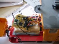
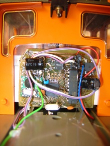
[[Datei:Locodoco v1 lgb 2060.jpg|thumb|left|200px|Loco decoder v1 in LGB 2060 ("Schöma Diesellok")]] | [[Datei:Locodoco v1 lgb 2060.jpg|thumb|left|200px|Loco decoder v1 in LGB 2060 ("Schöma Diesellok")]] | ||
The loco decoder | The loco decoder version 1 was a one layered printed circuit board with an AVR Microcontroller (Atmega32), a RFM12 radio transceiver, an L6202 Motor controller and several other Parts. After some testing and research in the model railroad community, it soon became clear, that especially load regulation is a feature which needed to be added to the controller. Furthermore the 78L05 power regulator (100mA) simply didn't provide enough power for smoke generators and servos. | ||
=== | === Loco decoder version 2 === | ||
The 2nd Version of the Loco decoder is currently under development. For more information about the device(s) see [[Locodoco/Loco_Decoder]]. | |||
== Waypoint transmitter == | == Waypoint transmitter == | ||
| Zeile 63: | Zeile 70: | ||
The waypoint transmitter fits underneath (or better said into) a single track brick of the standard LGB track and is visually almost completely hidden (just the transmitter diode peeking out). It consists of an infrared transceiver, an Attiny45 (or pin-compatible processor), a voltage regulator (78L05) and some capacitors. The device is designed to be powered by the track, which also makes it suitable for "mobile" track layouts. | The waypoint transmitter fits underneath (or better said into) a single track brick of the standard LGB track and is visually almost completely hidden (just the transmitter diode peeking out). It consists of an infrared transceiver, an Attiny45 (or pin-compatible processor), a voltage regulator (78L05) and some capacitors. The device is designed to be powered by the track, which also makes it suitable for "mobile" track layouts. | ||
» For more information about position tracking, see [[Locodoco/Position_Tracking|this page]]. | |||
== Turnout controller == | == Turnout controller == | ||
The turnout controller is a piece of hardware that... well, controls turnouts. There will be several different versions available - some with RFM12 modules, some with infrared transistors to receive commands. Both with different amounts of outputs (for driving more than one turnout or n-way turnouts). | The turnout controller is a piece of hardware that... well, controls turnouts. There will be several different versions available - some with RFM12 modules, some with infrared transistors to receive commands. Both with different amounts of outputs (for driving more than one turnout or n-way turnouts). | ||
== State of the Project == | == State of the Project == | ||
=== Done so far === | === Done so far === | ||
* [[Locodoco/Webinterface|Webinterface]]: proof of concept webinterface done | |||
* [[Locodoco/Loco_Decoder|Loco decoder v2]]: Impedance adjusted, schematics updated | |||
* Load regulation of the [[Locodoco/Loco_Decoder|Loco decoder v2]] tested - needs further tuning; impedance too high | |||
* [[Nakkaloader]] flashed & tested on the [[Locodoco/Loco_Decoder|Loco decoder v2]] - runs like a charme | |||
* [[Locodoco/Loco_Decoder|Loco decoder v2]] prototype built & currently undergoing testing | |||
* Loco decoder Prototype board built & tested in LGB 2033 and 2060 | * Loco decoder Prototype board built & tested in LGB 2033 and 2060 | ||
* First decoders installed and proven to be working stable | * First decoders installed and proven to be working stable | ||
* First pieces of software tested and run | * First pieces of software tested and run | ||
* Finished work bootloader to wirelessly update the firmware of the controller | * Finished work bootloader to wirelessly update the firmware of the controller | ||
* Developed & tested track nodes (for positioning information) | |||
=== To be done === | === To be done === | ||
'''Basic stuff''' | '''Basic stuff''' | ||
* Develop a turnout controller (Hard- and Software) | * Develop a turnout controller (Hard- and Software) | ||
* | * <strike> Develop a controlling device (currently a simple piece of software on a pc)</strike> | ||
* Develop a web gui for controlling Locos via Smartphones, Tablets & PCs | |||
'''Nifty stuff''' | '''Nifty stuff''' | ||
* Implement automatic track setup detection (i.e. let a loco drive along the track and scan all waypoints). This is necessary to enable the selection of the next turnout stage. | * Implement automatic track setup detection (i.e. let a loco drive along the track and scan all waypoints). This is necessary to enable the selection of the next turnout stage. | ||
* Experiment with accelerometer track recognition | * Experiment with accelerometer track recognition (» [https://en.wikipedia.org/wiki/Inertial_navigation_system see here]) | ||
=== Related work === | === Related work === | ||
| Zeile 166: | Zeile 103: | ||
* [http://usuaris.tinet.cat/fmco/home_en.htm Some more devices...] - Interface boards for the "Lokmaus" controller and some other useful devices. | * [http://usuaris.tinet.cat/fmco/home_en.htm Some more devices...] - Interface boards for the "Lokmaus" controller and some other useful devices. | ||
[[Kategorie:Microcontroller]] [[Kategorie:Datenfunk_mit_dem_Microcontroller]] | [[Kategorie:Microcontroller]] [[Kategorie:Datenfunk_mit_dem_Microcontroller]] | ||
{{LocodocoNavigation}} | |||
Aktuelle Version vom 8. April 2017, 00:12 Uhr
| locodoco Release status: experimental [box doku] | |
|---|---|
| |
| Description | An open source model railroad control infrastructure. |
| Author(s) | Soeren |
| Platform | AVR Microcontrollers |
| License | GPL |
| Download | Github |
Components & Building Blocks[Bearbeiten | Quelltext bearbeiten] |
About Locodoco[Bearbeiten | Quelltext bearbeiten]
Locodoco is an open source (Soft- and Hardware) project that lets you control model trains and automate train movements. The Project consist of several Hard- and Software components. In the first stage of this project's development a "loco decoder" was built. This piece of hardware lets you control motor throttle, lights and other functions of a loco via data transmissions.
Motivation[Bearbeiten | Quelltext bearbeiten]
There simply wasn't an open implementation that suited my needs. There is a well-developed open source project that implements DCC (Open DCC). Unfortunately DCC by nature doesn't provide features like sending transmissions from locos to the controller - well, actually it does, but this system would then be called RailCom©™® and is covered by patents - the opendcc project recently had to stop supporting it because the law situation was "uncertain".
Another goal I want to achieve is simplicity. A typical use case for this system is a plug-and-play setup where you simply stick all the track pieces together and plug in the power. In current implementations this works as well - turnouts get their signal from the track just like the locos do. The only disadvantage is that you'll have to remember or note turnout numbers in your control panel. The ability I wanted to add to model railroading is to make the process of switching a turnout more intuitive. Once this system is fully implemented you'll be able to select the next turnout on the way of a loco.
Features & Advantages[Bearbeiten | Quelltext bearbeiten]
Usual DCC systems aren't designed for mobile setups. Consider track occupancy detectors for example: To make use of them, you'll need to run wires from these devices back to your base station or even cut the track at some parts of your setup. Since these devices weren't even considered by the DCC standard definition, they possibly won't cooperate with hardware from other vendors, so you're pretty much bound to buying equipment from this particular vendor.
Waypoints & Positioning information[Bearbeiten | Quelltext bearbeiten]
Waypoints along the track (beacons) transmit an unique ID via infrared diodes to bypassing locos. This allows locos to transmit their position, direction and speed to the controlling devices. It may also be possible to utilize an accelerometer for more precise acceleration, deceleration information and positioning.
Independent power supply[Bearbeiten | Quelltext bearbeiten]
Unlike usual systems, locos equipped with a locodoco controller can run on any track that provides between 8 and 30 Volts power AC and DC. It is possible to mix usual DCC systems with this system and have locodoco equipped locos run on DCC powered track. The only disadvantage is that you can't control DCC locos with controllers for the locodoco system. It should be possible to let locodoco Trains accept commands from DCC, though this is a question of software development - the hardware is ready for it ;-)
Speed calibration[Bearbeiten | Quelltext bearbeiten]
With two position beacons in a known distance in between one can easily distinguish the speed of a running train. It is possible to "calibrate" speed levels and control locos by setting their _real_ speed (in contrast to a percentage level as it is the case with current systems).
This feature also allows for implementing beacons that send commands to throttle or halt locos - for example a signal sending the command "stop 1 meter ahead" - a beacon sending "speed limit 1cm/s for the next 3 meters" in front of a sharp curve...
Fully automated setup[Bearbeiten | Quelltext bearbeiten]
With position information and the possibility to control actual speeds, one can build compeletely automated model train setups. All one needs is a set of simple decisions (i.e. "if loco x is at position y, switch turnout 7 to right") and a controlling unit that sends commands to the locos accordingly.
Loco decoder[Bearbeiten | Quelltext bearbeiten]
First prototype (aka Version 1)[Bearbeiten | Quelltext bearbeiten]
The loco decoder version 1 was a one layered printed circuit board with an AVR Microcontroller (Atmega32), a RFM12 radio transceiver, an L6202 Motor controller and several other Parts. After some testing and research in the model railroad community, it soon became clear, that especially load regulation is a feature which needed to be added to the controller. Furthermore the 78L05 power regulator (100mA) simply didn't provide enough power for smoke generators and servos.
Loco decoder version 2[Bearbeiten | Quelltext bearbeiten]
The 2nd Version of the Loco decoder is currently under development. For more information about the device(s) see Locodoco/Loco_Decoder.
Waypoint transmitter[Bearbeiten | Quelltext bearbeiten]
A waypoint transmitter consists of a tiny AVR microcontroller that continuously transmits the same sequence of bits while it is turned on. An infrared LED connected to one of the AVR's output drivers can be installed in turnouts and normal track to mark a position.
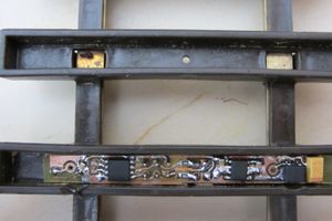
The waypoint transmitter fits underneath (or better said into) a single track brick of the standard LGB track and is visually almost completely hidden (just the transmitter diode peeking out). It consists of an infrared transceiver, an Attiny45 (or pin-compatible processor), a voltage regulator (78L05) and some capacitors. The device is designed to be powered by the track, which also makes it suitable for "mobile" track layouts.
» For more information about position tracking, see this page.
Turnout controller[Bearbeiten | Quelltext bearbeiten]
The turnout controller is a piece of hardware that... well, controls turnouts. There will be several different versions available - some with RFM12 modules, some with infrared transistors to receive commands. Both with different amounts of outputs (for driving more than one turnout or n-way turnouts).
State of the Project[Bearbeiten | Quelltext bearbeiten]
Done so far[Bearbeiten | Quelltext bearbeiten]
- Webinterface: proof of concept webinterface done
- Loco decoder v2: Impedance adjusted, schematics updated
- Load regulation of the Loco decoder v2 tested - needs further tuning; impedance too high
- Nakkaloader flashed & tested on the Loco decoder v2 - runs like a charme
- Loco decoder v2 prototype built & currently undergoing testing
- Loco decoder Prototype board built & tested in LGB 2033 and 2060
- First decoders installed and proven to be working stable
- First pieces of software tested and run
- Finished work bootloader to wirelessly update the firmware of the controller
- Developed & tested track nodes (for positioning information)
To be done[Bearbeiten | Quelltext bearbeiten]
Basic stuff
- Develop a turnout controller (Hard- and Software)
Develop a controlling device (currently a simple piece of software on a pc)- Develop a web gui for controlling Locos via Smartphones, Tablets & PCs
Nifty stuff
- Implement automatic track setup detection (i.e. let a loco drive along the track and scan all waypoints). This is necessary to enable the selection of the next turnout stage.
- Experiment with accelerometer track recognition (» see here)
Related work[Bearbeiten | Quelltext bearbeiten]
- opendcc is a project implementing an open source dcc stack and various hardware devices.
- MERG's DCC Devices - lots of open source DCC hardware devices
- Some more devices... - Interface boards for the "Lokmaus" controller and some other useful devices.
Locodoco Project | Position tracking system | Loco decoder | Webinterface


