Locodoco/Position Tracking
Intro
In other model railroad automation systems, track occupation detection is usually done by occupancy detectors that measure the resistance of the two rails - with magnets and reed contacts - or infrared light barriers. These devices either need some additional wiring back to the controller to give feedback or send their information back to the track - however they all aren't as portable and require extensive (and visible) modifications.
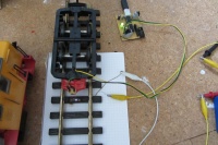
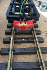
Since the Locodoco onboard decoder for the locos utilizes a radio transmitter anyway, it is possible for a loco to send this piece of information back to the controller itself. The locos are equipped with an infrared transceiver which makes them able to read the codes that the waypoint transmitters emit.
Waypoint Transmitter
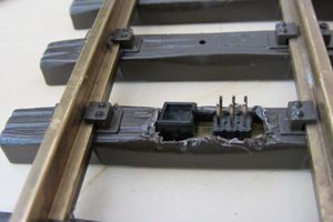
A waypoint transmitter consists of a tiny AVR microcontroller that continuously transmits the same sequence of bits while it is turned on. An infrared LED connected to one of the AVR's output drivers can be installed in turnouts and normal track to mark a position.
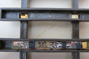
The waypoint transmitter fits underneath (or better said into) a single track brick of the standard LGB track and is visually almost completely hidden (just the transmitter diode peeking out). It consists of an infrared transceiver, an Attiny45 (or pin-compatible processor), a voltage regulator (78L05) and some capacitors. The device is designed to be powered by the track, which also makes it suitable for "mobile" track layouts.
Speed measurement
Given the distance of two waypoints is known and the speed of the loco is constant, one can measure how fast the loco is running. When making this distance very small, slight accelleration or decelleration of the loco running over the two points may be interpolated or ignored. The Waypoint Transmitter has some additional unconnected pins, which may be used for additional transmitter diodes sending a different code.
Protocol
Waypoint transmitters emit the code at a rate of 4800 bit/s. At each sequence, the waypoint transmitter sends out 32 bits containing its unique ID (16 bits) plus 16 additional bits that consist of the crc16 checksum. The overhead from the uart protocol adds 8 more bits (1 start + 1 stop bit for each of the 4 Bytes).
In detail, the sequence looks as follows:
[ 16b UUID | 16b CRC16 ]
Assuming the range at which the loco passing the waypoint transmitter is in the correct position for receiving the sequence is 1cm (d in Fig. 1), 40 bits are sent per beacon at each broadcast, then the maximum speed at which the system can reliably receive information is 0.96m/s. Note that we have to assume that at least 5 Bytes (50bits on the channel) have to be transferred correctly so the receiver may reliably detect them.
Locodoco Project | Position tracking system | Loco decoder | Webinterface


