Borg3d/en: Unterschied zwischen den Versionen
Keine Bearbeitungszusammenfassung |
|||
| Zeile 6: | Zeile 6: | ||
* 8x8x8 LEDs | * 8x8x8 LEDs | ||
* every LED can be controlled | * every LED can be controlled individually | ||
* One [[Laborboard]] with ATMega32 as controller | * One [[Laborboard]] with ATMega32 as controller | ||
* build by Martin Ongsiek | * build by Martin Ongsiek | ||
===Photos | ===Photos and videos=== | ||
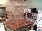
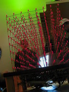
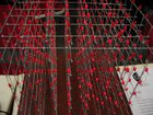
[[Bild:Borg-3d.jpg|140px]] | [[Bild:Borg-3d.jpg|140px]] | ||
| Zeile 20: | Zeile 20: | ||
===Hardware=== | ===Hardware=== | ||
The | The Borg is controlled through an Atmel ATMega32. It has interfaces for RS232, [[CAN]] bus and for two joysticks (the old digital ones from the C64). | ||
The 512 LEDs are controlled | The 512 LEDs are controlled time-multiplexed (matrix wiring). This is realized through 8 planes of 64 LEDs, which can be controlled one per timeintervall. The planes are switched about 1000 times per second, so it seems like all 512 are controlled individually at the same time with 4 brightness levels available. | ||
At the moment there is no official schematic, pcb or kit available, but you can | At the moment there is no official schematic, pcb or kit available, but you can have a look at the schematics made for our prototypes. | ||
Find them in our subversion repository [https://rl.das-labor.org/trac/browser/microcontroller/doc/Layouts/borg-3d here] (schematics and layout) | |||
[https://rl.das-labor.org/trac/browser/microcontroller/doc/Layouts/borg-3d | |||
Contact us if you want to build such a Borg, so we can hint you at a thing or two. As the first prototypes were not perfect, there are several optimizations now, which are not documented. | |||
The page '''[[Build a borg 3d]]''' | The page '''[[Build a borg 3d]]''' describes how the Borg is build. | ||
===Software=== | ===Software=== | ||
At the time being all animations on the Borg 3d are live rendered. There a no videos and a PC is not needed. You only have to plug in the power connector to get it up and running. A support for videos and especially for music visualization is planed but not implemented. It is also planed to build movies with a graphical tool. | |||
The complete software is written in | The complete software is written in C for the avr-gcc and can be found in our [[Subversion]] at [http://roulette.das-labor.org/svnview/microcontroller/src-atmel/borg/borg-3d microcontroller/borg/borg-3d] directory. | ||
====Simulator==== | ====Simulator==== | ||
To develop new animation on a | To develop new animation on a PC, we also built a simulator, which is programmed with the good old opengl-framework GLUT. | ||
It is divided into threads | It is divided into threads: | ||
* Thread 1 displays the frame-buffer, that is like the original, in the opengl. | * Thread 1 displays the frame-buffer, that is like the original, in the opengl. | ||
* Thread 2 is like the original with the difference , that the wait routine is replaces and other files are included. | * Thread 2 is like the original with the difference , that the wait routine is replaces and other files are included. | ||
This | This does work so well that we normally cut and paste the simulator animation in the source of the original and have it running. | ||
The Simulator can be found in our [[Subversion]] at [http://roulette.das-labor.org/svnview/microcontroller/src-atmel/borg/borg-3d-apiSimulator microcontroller/borg/borg-3d-apiSimulator] directory. | The Simulator can be found in our [[Subversion]] at the [http://roulette.das-labor.org/svnview/microcontroller/src-atmel/borg/borg-3d-apiSimulator microcontroller/borg/borg-3d-apiSimulator] directory. | ||
===History=== | ===History=== | ||
Martin | Martin had found this page of [http://www.jamesclar.com/product/2003/3dcubev3/index.html james clar] long before he had ever been to the Labor and met Peter. He was exalted and wanted to build such a cube on his own. He also wanted to have a real 3d display and to make something useful with modern micro controllers. So he went to the Labor's first microcontroller workshop and soldered his own [[Laborboard]]. | ||
At first he build a 3x3x3 prototype to get a | At first he build a 3x3x3 prototype to get a clue how to do the wiring of the LEDs and the cube. | ||
After the 3x3x3 borg worked fine | After the 3x3x3 borg worked fine he started building the first 8x8x8 Borg. The amount of work for the soldering and the driver board and so on was much higher than expected. | ||
== Exhibitions == | == Exhibitions == | ||
Version vom 8. September 2007, 20:18 Uhr
Borg 3d
Facts
- 8x8x8 LEDs
- every LED can be controlled individually
- One Laborboard with ATMega32 as controller
- build by Martin Ongsiek
Photos and videos
Hardware
The Borg is controlled through an Atmel ATMega32. It has interfaces for RS232, CAN bus and for two joysticks (the old digital ones from the C64).
The 512 LEDs are controlled time-multiplexed (matrix wiring). This is realized through 8 planes of 64 LEDs, which can be controlled one per timeintervall. The planes are switched about 1000 times per second, so it seems like all 512 are controlled individually at the same time with 4 brightness levels available.
At the moment there is no official schematic, pcb or kit available, but you can have a look at the schematics made for our prototypes. Find them in our subversion repository here (schematics and layout)
Contact us if you want to build such a Borg, so we can hint you at a thing or two. As the first prototypes were not perfect, there are several optimizations now, which are not documented.
The page Build a borg 3d describes how the Borg is build.
Software
At the time being all animations on the Borg 3d are live rendered. There a no videos and a PC is not needed. You only have to plug in the power connector to get it up and running. A support for videos and especially for music visualization is planed but not implemented. It is also planed to build movies with a graphical tool.
The complete software is written in C for the avr-gcc and can be found in our Subversion at microcontroller/borg/borg-3d directory.
Simulator
To develop new animation on a PC, we also built a simulator, which is programmed with the good old opengl-framework GLUT. It is divided into threads:
- Thread 1 displays the frame-buffer, that is like the original, in the opengl.
- Thread 2 is like the original with the difference , that the wait routine is replaces and other files are included.
This does work so well that we normally cut and paste the simulator animation in the source of the original and have it running.
The Simulator can be found in our Subversion at the microcontroller/borg/borg-3d-apiSimulator directory.
History
Martin had found this page of james clar long before he had ever been to the Labor and met Peter. He was exalted and wanted to build such a cube on his own. He also wanted to have a real 3d display and to make something useful with modern micro controllers. So he went to the Labor's first microcontroller workshop and soldered his own Laborboard.
At first he build a 3x3x3 prototype to get a clue how to do the wiring of the LEDs and the cube.
After the 3x3x3 borg worked fine he started building the first 8x8x8 Borg. The amount of work for the soldering and the driver board and so on was much higher than expected.
Exhibitions
- Linux Tage Essen 2005 (3. - 4.12.2005) - http://essen.linux-tage.linec.de/
- 22. Chaos Communication Congress (26. - 30.12.2005) - http://events.ccc.de/congress/2005/?language=de
- pong.mythos (10.02.2006 - 01.05.2006) - http://www.pong-mythos.net/
- Games Convention / pong.mythos (24.08.2006 - 27.08.2006)
- 23. Chaos Communication Congress (26. - 30.12.2006) - http://events.ccc.de/congress/2006/
- Kornhausforum in Bern / pong.mythos (17.08.2007 – 16.09.2007) - http://www.pong-mythos.net/


