VP5500/serial howto: Unterschied zwischen den Versionen
Aus LaborWiki
Soeren (Diskussion | Beiträge) K (Die Seite wurde neu angelegt: „left|thumb|100px|Serial pinout Open the battery cover and disconnect the battery. Then solder 3 wires to the RX, TX and GND pins: [[…“) |
Soeren (Diskussion | Beiträge) KKeine Bearbeitungszusammenfassung |
||
| Zeile 11: | Zeile 11: | ||
After re-assembling all the stuff, it should look somewhat similar to this... | After re-assembling all the stuff, it should look somewhat similar to this... | ||
[[Bild:Vp5500_serial_howto_0003.jpeg]] | [[Bild:Vp5500_serial_howto_0003.jpeg]] | ||
[[VP5500|<< back to VP5500 main page]] | |||
Aktuelle Version vom 23. März 2010, 00:12 Uhr
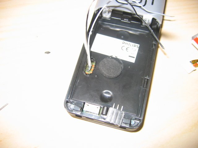
Open the battery cover and disconnect the battery. Then solder 3 wires to the RX, TX and GND pins:

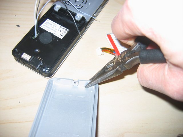
Break of a tiny bit of the back cover. Try to not break the center pin of the back cover since this gives mechanical support for the screw you need to reattach later on.

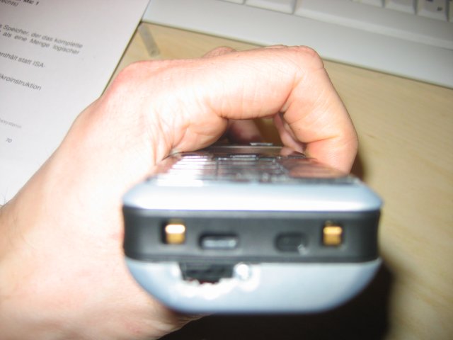
After re-assembling all the stuff, it should look somewhat similar to this...

