SDRT: Unterschied zwischen den Versionen
Siro (Diskussion | Beiträge) (software defined radio transmitter) |
Siro (Diskussion | Beiträge) (moved to obsolete) |
||
| (Eine dazwischenliegende Version desselben Benutzers wird nicht angezeigt) | |||
| Zeile 1: | Zeile 1: | ||
{{ProjektInfoBox | {{ProjektInfoBox | ||
|name = SDRT | |name = SDRT | ||
|status = | |status = obsolete | ||
|image = | |image = | ||
|description = use the VGA port to transmit I/Q signals on any frequency | |description = use the VGA port to transmit I/Q signals on any frequency | ||
| Zeile 20: | Zeile 20: | ||
The board has a 50Ohms SMA connector transmitting about 0dBm using VGA signals (0.7Vpp). | The board has a 50Ohms SMA connector transmitting about 0dBm using VGA signals (0.7Vpp). | ||
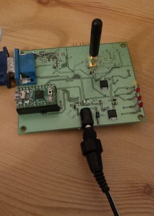
== | [[Datei:Sdrt_top.jpg|thumb]] | ||
== Board == | |||
=== Overview === | |||
* VGA DSUB connector, baseband input | |||
* power jack DC 5.5V - 6.0V, > 300mA | |||
* 4 LEDS | |||
** power | |||
** teensy alive | |||
** rf enabled | |||
** unused | |||
* teensy | |||
* SMA connector, rf output | |||
* switch (rf disable/enable) | |||
=== Clock === | |||
26 Mhz TCXO +-2 ppm 1.8V | |||
=== Low pass === | |||
I'm using one 9Mhz 3rd order Bessel low pass filter on each channel. This isn't included in the schematics. | |||
All three channels are terminated using 75 Ohms. | |||
=== SPI === | |||
The SPI interface should have series resistance of more than 50 Ohms. | |||
=== ADRF6701 === | |||
* reference design | |||
* internal vco and pll is used | |||
* LO path is disabled | |||
* input multiplier 1:1 | |||
* internal LO divider 1:4 | |||
* fin: 26Mhz ac coupled | |||
* lo output freq: | |||
fout = fin / 4 * ( INT + (mod / frac) ) | |||
where: | |||
INT, MOD, FRAC are register values | |||
== | == Layout == | ||
todo | todo | ||
== TODOs == | == TODOs == | ||
| Zeile 37: | Zeile 69: | ||
* use a display to show the current freq. | * use a display to show the current freq. | ||
* rotary switch | * rotary switch | ||
== Summary == | |||
* new i/q filter design is critical | |||
* adrf6703 doesn't work as intended (write only, no debug pins) | |||
* new design done -> this part is now obsolete | |||
== Links == | == Links == | ||
Aktuelle Version vom 23. April 2013, 13:10 Uhr
| SDRT Release status: obsolete [box doku] | |
|---|---|
| Description | use the VGA port to transmit I/Q signals on any frequency |
| Author(s) | siro (siro) |
| Last Version | 0.1 () |
| License | GPL |
Software Defined Radio Transmitter[Bearbeiten | Quelltext bearbeiten]
Description[Bearbeiten | Quelltext bearbeiten]
Hardware to transmit anything on any frequency. That means any information / modulation can be transmited on a channel between 750 and 1150 Mhz, which is the possible internal PLL frequency-range for ADRF6701. The I/Q signals are feed through a VGA-compatible 15pole-DSUB connector.
This board is intended to be used with VGAtoBaseband.
This is a prototype with a teensy controlling the ADRF6701. The frequency can be adjusted using a USB terminal connection.
The board has a 50Ohms SMA connector transmitting about 0dBm using VGA signals (0.7Vpp).
Board[Bearbeiten | Quelltext bearbeiten]
Overview[Bearbeiten | Quelltext bearbeiten]
- VGA DSUB connector, baseband input
- power jack DC 5.5V - 6.0V, > 300mA
- 4 LEDS
- power
- teensy alive
- rf enabled
- unused
- teensy
- SMA connector, rf output
- switch (rf disable/enable)
Clock[Bearbeiten | Quelltext bearbeiten]
26 Mhz TCXO +-2 ppm 1.8V
Low pass[Bearbeiten | Quelltext bearbeiten]
I'm using one 9Mhz 3rd order Bessel low pass filter on each channel. This isn't included in the schematics. All three channels are terminated using 75 Ohms.
SPI[Bearbeiten | Quelltext bearbeiten]
The SPI interface should have series resistance of more than 50 Ohms.
ADRF6701[Bearbeiten | Quelltext bearbeiten]
- reference design
- internal vco and pll is used
- LO path is disabled
- input multiplier 1:1
- internal LO divider 1:4
- fin: 26Mhz ac coupled
- lo output freq:
fout = fin / 4 * ( INT + (mod / frac) )
where:
INT, MOD, FRAC are register values
Layout[Bearbeiten | Quelltext bearbeiten]
todo
TODOs[Bearbeiten | Quelltext bearbeiten]
- use ADRF6755
- shrink board size
- don't use eeprom 24C02
- don't use teensy, maybe Attiny
- don't use sot-123 diodes
- rf power amplifier
- use a display to show the current freq.
- rotary switch
Summary[Bearbeiten | Quelltext bearbeiten]
- new i/q filter design is critical
- adrf6703 doesn't work as intended (write only, no debug pins)
- new design done -> this part is now obsolete
