Benutzer:Hansinator: Unterschied zwischen den Versionen
Aus LaborWiki
Keine Bearbeitungszusammenfassung |
Keine Bearbeitungszusammenfassung |
||
| Zeile 51: | Zeile 51: | ||
== | == VacuBot == | ||
<pre> | <pre> | ||
==== ATMEGA8 PIN CONFIGURATION ==== | ==== MOTORCTRL ATMEGA8 PIN CONFIGURATION ==== | ||
Names in () are or were planned. | Names in () are or were planned. | ||
| Zeile 102: | Zeile 102: | ||
** FREE | ** FREE | ||
PD6, PD7 | PD6, PD7 | ||
==== MOTORCTRL MISC STUFF ==== | |||
* Encoder IR-Diodes 1k ?? (re-evaluate) | |||
* How to connect phototransistors? I can remeber they had 1k resistors on em. (See on orig. board) | |||
* Use 1/8th Voltage divider (14.4 / 8 = 1.6V -> 12 cells * 1.5V max = 18V -> 18/8 = 2,25V) | |||
* Use logic level fets for vacuum and brush motor turnon/off | |||
* Reverse engineer loader circuit, reuse relais if it could cut loader power | |||
* Use L6202 motor driver ICs | |||
==== MAINBOARD SPECS ==== | |||
* Use the fat 128k flash / 16k ram 40pin DIP Atmega | |||
* Probably use a switched power supply -> ask peter for that chip | |||
* Think of creative use for the big fat atmel | |||
* Use rfm12 | |||
</pre> | </pre> | ||
Version vom 2. November 2008, 14:22 Uhr
Hallo, Willkommen auf meiner Seite!
Ich bin der unglaubliche Hans, beuget euch meiner Macht!
- Ich bastele momentan an Robotern, siehe unten
- Ich programmiere gelegentlich Animationen für den FarbBorg3d
- Alle farbigen Borgs bekommen Plasmaeffekte von mir verpasst ;-)
- Ich habe an der rfm12lib und dem rfm12usb mitgebastelt.. ausserdem benutze ich rfm12s in meinen Projekten
- Manchmal findet man mich kopfüber hängend an Doppel-T-Trägern (ich mache Matis Zügen Konkurrenz!)
- Ich habe schon mal ein Kind gelötet...
Robolord Hansinator
I'm da master of da Robotaaaaaaaaaz!! KILL ALL HUMANS !! brrrrrrrrrrrrz.
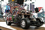
Rechts sieht man meinen aktuelles Roboterprojekt, den Shr0dBot.
Vielen Dank an Mati für das Foto!
Special Greetz
Jetzt möchte ich noch einige nette Leute grüßen! (Zufällig sortiert)
DU fehlst hier, glaubst aber, ich würde dich auch grüßen wollen, hätte ich dich nicht vergessen?
Trag dich halt selber ein...
Menschen mit nicht vorhandenen Benutzerseiten werden nicht verlinkt.
Kunst im Lab
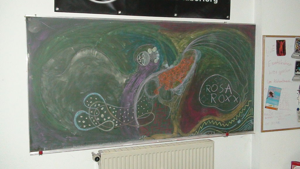
Das habe ich mal gemalt, als ich die bunte Kreide fand.
VacuBot
==== MOTORCTRL ATMEGA8 PIN CONFIGURATION ====

Names in () are or were planned.
Pins marked with [in] are inputs, whilst the ones marked with [out] are outputs.
All other pins make use of their respective special function(s).


** GENERIC
XTAL1,2	- 16MHZ, no capacitors
VCC,
AVCC,
AREF	- +5V 7805, 100nF
GND	- COMMON GROUND


** PORT B
0 - VACCUUM CLEANER DRIVE ON/OFF [out]
1 - PWM MOTOR 1 [OC1A]
2 - ISP [SPI SS], PWM MOTOR 2 [OC1B]
3 - ISP [SPI MOSI], WHEEL/MOTOR 1 LIFTOFF DETECTOR [in]
4 - ISP [SPI MISO], WHEEL/MOTOR 2 LIFTOFF DETECTOR [in]
5 - ISP [SPI SCK], FRONT LIFTOFF DETECTOR [in]
6 - XTAL1
7 - XTAL2

** PORT C
0 - BATTERY POWER DIVIDER (1nF load) [ADC0]
1 - MOTOR 1 CURRENT MEASUREMENT (capacitive load?) [ADC1]
2 - MOTOR 2 CURRENT MEASUREMENT (capacitive load?) [ADC2]
3 - ACCU LOADER ON/OFF [out]
4 - SPI SLAVE [SDA]
5 - SPI SLAVE [SCL]
6 - RESET, PRELIMINARY (COULD BE BRUSH DRIVE ON/OFF [out])


** PORT D
0 - MOTOR 2 FORWARD [out]
1 - MOTOR 2 REVERSE [out]
2 - ENCODER A [in]
3 - ENCODER B [in]
4 - MOTOR 1 FORWARD [out]
5 - MOTOR 1 REVERSE [out]
6 - BRUSH DRIVE ON/OFF [out]
7 - FREE


** FREE
PD6, PD7


==== MOTORCTRL MISC STUFF ====

* Encoder IR-Diodes 1k ?? (re-evaluate)
* How to connect phototransistors? I can remeber they had 1k resistors on em. (See on orig. board)
* Use 1/8th Voltage divider (14.4 / 8 = 1.6V -> 12 cells * 1.5V max = 18V -> 18/8 = 2,25V)
* Use logic level fets for vacuum and brush motor turnon/off
* Reverse engineer loader circuit, reuse relais if it could cut loader power
* Use L6202 motor driver ICs

==== MAINBOARD SPECS ====

* Use the fat 128k flash / 16k ram 40pin DIP Atmega
* Probably use a switched power supply -> ask peter for that chip
* Think of creative use for the big fat atmel
* Use rfm12

