Funkzecke: Unterschied zwischen den Versionen
Soeren (Diskussion | Beiträge) KKeine Bearbeitungszusammenfassung |
Keine Bearbeitungszusammenfassung |
||
| (4 dazwischenliegende Versionen von 3 Benutzern werden nicht angezeigt) | |||
| Zeile 1: | Zeile 1: | ||
{{ProjektInfoBox | {{ProjektInfoBox | ||
|name | |name=funkzecke | ||
|status | |status=experimental | ||
|image | |image=Funkzecke_m8_0.png | ||
|description = Breakout board equipped with essential parts for your radio-controlled microcontroller project | |description=Breakout board equipped with essential parts for your radio-controlled microcontroller project | ||
|author | |author=[[Benutzer:Soeren|Soeren]] | ||
|version=0x0000 | |||
|version | |platform=AVR Microcontrollers | ||
|license=GPL | |||
|platform | |update= | ||
|license | |tags=Microcontroller & FPGAs, Funk, | ||
| | }} | ||
}} __NOTOC__ | __NOTOC__ | ||
[[Datei:Funkzecke_m8_1.png|thumb|left|120px|Funkzecke M8 from the Backside]] | [[Datei:Funkzecke_m8_1.png|thumb|left|120px|Funkzecke M8 from the Backside]] | ||
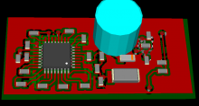
The "funkzecke" (German word creation meaning "radio tick") is a board that consists of essential parts for creating a radio-controlled microcontroller project. The first of its kind "funkzecke-m8" is basically a small breakout board with 15 usable IO pins for the Atmega8 (as well as pin-compatible controllers) which consists of a power supply, a microcontroller and a rfm12 radio transceiver. The entire board is optimized for size and measures approximately 22x43mm. | The "funkzecke" (German word creation meaning "radio tick") is a board that consists of essential parts for creating a radio-controlled microcontroller project. The first of its kind "funkzecke-m8" is basically a small breakout board with 15 usable IO pins for the Atmega8 (as well as pin-compatible controllers) which consists of a power supply, a microcontroller and a rfm12 radio transceiver. The entire board is optimized for size and measures approximately 22x43mm. | ||
| Zeile 17: | Zeile 17: | ||
This project clearly is not meant to be for beginners and expects the user to be able to solder SMD parts. Bootstrapping the Funkzecke-M8 is also not as trivial: Because there is no space left on the board, programming has to be done with soldered-on wires once and can then be done over the radio interface with the [[Nakkaloader]]. | This project clearly is not meant to be for beginners and expects the user to be able to solder SMD parts. Bootstrapping the Funkzecke-M8 is also not as trivial: Because there is no space left on the board, programming has to be done with soldered-on wires once and can then be done over the radio interface with the [[Nakkaloader]]. | ||
== | == First test == | ||
[[Bild:Gsm_gateway0.jpg|thumb|left|120px|Funkzecke attached to a GSM phone]]The first test of the PCB Layout was a success. I've made a double Layer PCB prototype and am using it for my private alarm system at home. When testing however I found that a crystal is mandatory for reliable USART communication, therefore I'll add the ability to add a quartz in the next revision. | |||
In addition I've created a DIL Version of the Funkzecke. The Layout files will be released once it has passed testing... | |||
[[Kategorie:Microcontroller]] | |||
[[Kategorie:Datenfunk mit dem Microcontroller]] | |||
Aktuelle Version vom 8. April 2017, 00:30 Uhr
| funkzecke Release status: experimental [box doku] | |
|---|---|

| |
| Description | Breakout board equipped with essential parts for your radio-controlled microcontroller project |
| Author(s) | Soeren |
| Last Version | 0x0000 () |
| Platform | AVR Microcontrollers |
| License | GPL |
The "funkzecke" (German word creation meaning "radio tick") is a board that consists of essential parts for creating a radio-controlled microcontroller project. The first of its kind "funkzecke-m8" is basically a small breakout board with 15 usable IO pins for the Atmega8 (as well as pin-compatible controllers) which consists of a power supply, a microcontroller and a rfm12 radio transceiver. The entire board is optimized for size and measures approximately 22x43mm.
This project clearly is not meant to be for beginners and expects the user to be able to solder SMD parts. Bootstrapping the Funkzecke-M8 is also not as trivial: Because there is no space left on the board, programming has to be done with soldered-on wires once and can then be done over the radio interface with the Nakkaloader.
First test[Bearbeiten | Quelltext bearbeiten]
The first test of the PCB Layout was a success. I've made a double Layer PCB prototype and am using it for my private alarm system at home. When testing however I found that a crystal is mandatory for reliable USART communication, therefore I'll add the ability to add a quartz in the next revision.
In addition I've created a DIL Version of the Funkzecke. The Layout files will be released once it has passed testing...

