Benutzer:Hansinator: Unterschied zwischen den Versionen
Aus LaborWiki
KKeine Bearbeitungszusammenfassung |
KKeine Bearbeitungszusammenfassung |
||
| Zeile 52: | Zeile 52: | ||
XTAL1,2 - 16MHZ, no capacitors | XTAL1,2 - 16MHZ, no capacitors | ||
VCC, | VCC, | ||
AVCC | AVCC - +5V, 100nF | ||
GND - COMMON GROUND | GND - COMMON GROUND | ||
| Zeile 74: | Zeile 73: | ||
4 - TWI SLAVE [SDA] | 4 - TWI SLAVE [SDA] | ||
5 - TWI SLAVE [SCL] | 5 - TWI SLAVE [SCL] | ||
6 - RESET | 6 - RESET | ||
| Zeile 84: | Zeile 83: | ||
4 - MOTOR 1 FORWARD [out] | 4 - MOTOR 1 FORWARD [out] | ||
5 - MOTOR 1 REVERSE [out] | 5 - MOTOR 1 REVERSE [out] | ||
6 - BRUSH DRIVE ON/OFF [out] | 6 - BRUSH DRIVE 1 ON/OFF [out] | ||
7 - | 7 - BRUSH DRIVE 2 ON/OFF [out] | ||
| Zeile 100: | Zeile 99: | ||
* Reverse engineer loader circuit, reuse relais if it could cut loader power | * Reverse engineer loader circuit, reuse relais if it could cut loader power | ||
* Use L6202 motor driver ICs | * Use L6202 motor driver ICs | ||
* Motor current: | |||
** Blocked motor draws max. ~800mA | |||
** Normal operation ~350mA | |||
** 0.1 ohm current sense resistors | |||
** Max ~80mV sense voltage | |||
** ~35mV in normal operation | |||
** 25 times amplification to use with adc @ 2.56V internal reference | |||
** Use lm358 opamp | |||
* What do the two diodes @ current sense / gnd do? | |||
They used: | They used: | ||
| Zeile 113: | Zeile 121: | ||
* Use rfm12 | * Use rfm12 | ||
</pre> | </pre> | ||
==== Hansinator's MotorCTRL Board ==== | |||
* Both L6202 are correctly connected to motor and atmega | |||
** Need a solutin for current sensing | |||
Version vom 4. Juli 2010, 05:30 Uhr
Hallo, Willkommen auf meiner Seite!
Was ich so mache:
- Ich bastele momentan an Robotern, siehe unten
- Ich programmiere manchmal Animationen für die Borgs
- Alle farbigen Borgs haben Plasmaeffekte von mir :-)
- Ich habe an der rfm12lib, dem rfm12usb und dem rfm12 Bootloader mitgebastelt.. ausserdem benutze ich rfm12s in meinen Projekten
- Ich bringe Design in das Wiki!
- Ich habe schon mal ein Kind gelötet...
Why Free Software usability tends to suck
Top 25 Most Dangerous Programming Errors
Java: how not to make a mess of stream handling
A Whirlwind Tutorial on Creating Really Teensy ELF Executables for Linux
Brainstorming
- HAP Version 0
Ein Protokoll zur Hausautomatisierung
Mein(e) Robo(s)
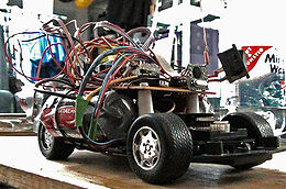
Rechts sieht man mein aktuelles Roboterprojekt, den Shr0dBot.
Vielen Dank an Mati für das Foto!
Kunst im Lab
Das habe ich mal gemalt, als ich die bunte Kreide fand.
VacuBot
==== MOTORCTRL ATMEGA8 PIN CONFIGURATION ====

Names in () are or were planned.
Pins marked with [in] are inputs, whilst the ones marked with [out] are outputs.
All other pins make use of their respective special function(s).


** GENERIC
XTAL1,2	- 16MHZ, no capacitors
VCC,
AVCC    - +5V, 100nF
GND	- COMMON GROUND


** PORT B
0 - VACCUUM CLEANER DRIVE ON/OFF [out]
1 - PWM MOTOR 1 [OC1A]
2 - ISP [SPI SS], PWM MOTOR 2 [OC1B]
3 - ISP [SPI MOSI], WHEEL/MOTOR 1 LIFTOFF DETECTOR [in]
4 - ISP [SPI MISO], WHEEL/MOTOR 2 LIFTOFF DETECTOR [in]
5 - ISP [SPI SCK], FRONT LIFTOFF DETECTOR [in]
6 - XTAL1
7 - XTAL2

** PORT C
0 - BATTERY POWER DIVIDER (1nF load) [ADC0]
1 - MOTOR 1 CURRENT MEASUREMENT (capacitive load?) [ADC1]
2 - MOTOR 2 CURRENT MEASUREMENT (capacitive load?) [ADC2]
3 - ACCU LOADER ON/OFF [out]
4 - TWI SLAVE [SDA]
5 - TWI SLAVE [SCL]
6 - RESET


** PORT D
0 - MOTOR 2 FORWARD [out]
1 - MOTOR 2 REVERSE [out]
2 - ENCODER A [in]
3 - ENCODER B [in]
4 - MOTOR 1 FORWARD [out]
5 - MOTOR 1 REVERSE [out]
6 - BRUSH DRIVE 1 ON/OFF [out]
7 - BRUSH DRIVE 2 ON/OFF [out]


** FREE
PD6, PD7


==== MOTORCTRL MISC STUFF ====

* Encoder IR-Diodes 1k ?? (re-evaluate)
* How to connect phototransistors? I can remeber they had 1k resistors on em. (See on orig. board)
* Use 1/8th Voltage divider (14.4 / 8 = 1.6V -> 12 cells * 1.5V max = 18V -> 18/8 = 2,25V)
* Use logic level fets for vacuum and brush motor turnon/off
* Reverse engineer loader circuit, reuse relais if it could cut loader power
* Use L6202 motor driver ICs
* Motor current:
** Blocked motor draws max. ~800mA
** Normal operation ~350mA
** 0.1 ohm current sense resistors
** Max ~80mV sense voltage
** ~35mV in normal operation
** 25 times amplification to use with adc @ 2.56V internal reference
** Use lm358 opamp
* What do the two diodes @ current sense / gnd do?

They used:
* L289 for motor control
* 14.4V motor power
* LM2565T switching power supply for logic

==== MAINBOARD SPECS ====

* Use the fat 128k flash / 16k ram 40pin DIP Atmega
* Probably use a switched power supply -> ask peter for that chip
* Think of creative use for the big fat atmel
* Use rfm12
Hansinator's MotorCTRL Board
- Both L6202 are correctly connected to motor and atmega
- Need a solutin for current sensing

