Daylight Indicator: Unterschied zwischen den Versionen
Soeren (Diskussion | Beiträge) KKeine Bearbeitungszusammenfassung |
Soeren (Diskussion | Beiträge) K (-vvv) |
||
| Zeile 1: | Zeile 1: | ||
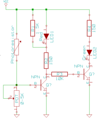
[[Bild:Daylightindicator_circuit.png|thumb|200px|left|This is circuit for the daylight indicator]] | [[Bild:Daylightindicator_circuit.png|thumb|200px|left|This is circuit for the daylight indicator]] | ||
'''Geeks are a bit like Vampires - they usually fear the daylight.''' Now since the Labor has gotten [http://www.das-labor.org/blog/index.php/2009/02/23/fight-the-daylight/ new fancy window blinds], it has become hard to detect whether the big, bright, evil [http://ars.userfriendly.org/cartoons/?id=19991208 daystar] shines or not. Therefore [[Benutzer:Soeren|Soeren]] has built a little indicator light to display a daylight-threat warning (red light) or green light whenever it is safe to step outside ;-) | '''Geeks are a bit like Vampires - they usually fear the daylight.''' Now since the Labor has gotten [http://www.das-labor.org/blog/index.php/2009/02/23/fight-the-daylight/ new fancy window blinds], it has become hard to detect whether the big, bright, evil [http://ars.userfriendly.org/cartoons/?id=19991208 daystar] shines or not. Therefore [[Benutzer:Soeren|Soeren]] has built a little indicator light to display a daylight-threat warning (red light) or green light whenever it is safe to step outside ;-) | ||
The circuit is quite simple: When the resistance of the [http://en.wikipedia.org/wiki/Photoresistor photoresistor] falls beneath a certain level, the left NPN transistor gets fed with enough current and lets the current flow through the red LED. If the red LED is turned on, there isn't enough current for the right side transistor, so that one shuts off. | |||
The sensivity for the photoresistor is adjustable via the potentiometer. It acts as a pull-down Resistor for the left transistor when the photoresistor has a (comparably) high resistance. In order to prevent the red LED from lighting up, R1 is set in parallel so that there is not enough current left for the red LED to light up. | |||
All values in this circuit may vary depending on your setup and parts used. So if you want to rebuild this circuit, you should first test it on a breadboard before soldering it all together ;-) | |||
Version vom 13. März 2009, 09:24 Uhr
Geeks are a bit like Vampires - they usually fear the daylight. Now since the Labor has gotten new fancy window blinds, it has become hard to detect whether the big, bright, evil daystar shines or not. Therefore Soeren has built a little indicator light to display a daylight-threat warning (red light) or green light whenever it is safe to step outside ;-)
The circuit is quite simple: When the resistance of the photoresistor falls beneath a certain level, the left NPN transistor gets fed with enough current and lets the current flow through the red LED. If the red LED is turned on, there isn't enough current for the right side transistor, so that one shuts off. The sensivity for the photoresistor is adjustable via the potentiometer. It acts as a pull-down Resistor for the left transistor when the photoresistor has a (comparably) high resistance. In order to prevent the red LED from lighting up, R1 is set in parallel so that there is not enough current left for the red LED to light up.
All values in this circuit may vary depending on your setup and parts used. So if you want to rebuild this circuit, you should first test it on a breadboard before soldering it all together ;-)
