Laserprojector en: Unterschied zwischen den Versionen
Siro (Diskussion | Beiträge) (english version of "Laserprojector") |
Ex (Diskussion | Beiträge) Keine Bearbeitungszusammenfassung |
||
| (4 dazwischenliegende Versionen von einem anderen Benutzer werden nicht angezeigt) | |||
| Zeile 1: | Zeile 1: | ||
{{Workinprogress}}<!-- keine Inhalte vor diesem Kommentar! (Kopf-Banner) --> | {{Workinprogress}}<!-- keine Inhalte vor diesem Kommentar! (Kopf-Banner) --> | ||
[[ | [[Laserprojector|Deutsche Version]] | ||
{{ProjektInfoBox | {{ProjektInfoBox | ||
| Zeile 10: | Zeile 10: | ||
|username = siro | |username = siro | ||
|version = 0.2 | |version = 0.2 | ||
|update = | |update = 30.12.2010 | ||
|platform = | |platform = | ||
| Zeile 21: | Zeile 21: | ||
<b>Concept :</B> Build a laserprojector as easy as possible<br /> | <b>Concept :</B> Build a laserprojector as easy as possible<br /> | ||
< | == Übersicht == | ||
<b>Max. Resolution</b>:256x256<br> | |||
<b>Refreshrate</b>:30Hz<br> | |||
<b>Colors</b>:1 (blau)<br> | |||
<b>Colordepth</b>: 256 (8-bit)<br> | |||
<b>Interfaces</b>: RS232, ??<br> | |||
<b>Reflectionunits</b>:2x Mirrorwheels, Asyncronmotor + DC-motor<br> | |||
<b>used Controllers</b>:ATmega169 + STM3210xx<br> | |||
== Basic Idea == | |||
An Atmega controlls 2 fast motors, checks keyboard input,controls GLCD and Power-Supply.<br> | An Atmega controlls 2 fast motors, checks keyboard input,controls GLCD and Power-Supply.<br> | ||
On each motor is a mirror-disk spinning to | On each motor is a mirror-disk spinning to deflect the laserlight.The first mirror deflects the light only in the horizontal layer, the second one deflects light on the vertical layer. I'm going to modulate the laser diode to draw images.<br /> | ||
== Syncronisationunit:== | |||
<b>obsolete</b><br> | |||
< | |||
</ | |||
Detects position of the laserbeam | Detects position of the laserbeam | ||
[[http://www.das-labor.org/trac/export/4063/microcontroller/src-atmel/laserproj/daily-build/eagle/ eagle Dateien im labor-svn]]<br> | [[http://www.das-labor.org/trac/export/4063/microcontroller/src-atmel/laserproj/daily-build/eagle/ eagle Dateien im labor-svn]]<br> | ||
<i> | <i>Better use a impedanceconveter, instead of voltage divieder.</i><br> | ||
<gallery> | <gallery> | ||
Datei:Laserproj syncschem.png| | Datei:Laserproj syncschem.png|schematics of syncronisationunit | ||
Datei:Laserproj syncboard.png|SMD-Board | Datei:Laserproj syncboard.png|SMD-Board of syncronisationunit | ||
</gallery> | </gallery> | ||
| Zeile 50: | Zeile 51: | ||
Versorgungsspannung: 3,7 bis 15 Volt (empfohlen 5 bis 12 Volt). | Versorgungsspannung: 3,7 bis 15 Volt (empfohlen 5 bis 12 Volt). | ||
</i> | </i> | ||
== Syncsensor == | |||
Two small IR-LEDs are emitting light onto the spinning mirrors. The deflected light changes the current at the "fototransistor". | Two small IR-LEDs are emitting light onto the spinning mirrors. The deflected light changes the current at the "fototransistor". | ||
< | == Saftyunit == | ||
<b>obsolete</b><br> | |||
The Saftyunit has to detect, that both mirrors are spinning fast enough, to prevent damage to anything in the laserbeam. The saftyunit cuts the laser power as soon as anything shows abnormal behavior.<b>This is a class 3 laser, able to burn wood/paper/flesh even in a few meters distance !</b> | The Saftyunit has to detect, that both mirrors are spinning fast enough, to prevent damage to anything in the laserbeam. The saftyunit cuts the laser power as soon as anything shows abnormal behavior.<b>This is a class 3 laser, able to burn wood/paper/flesh even in a few meters distance !</b> | ||
== Controlunit == | |||
Connected to the controlunit are GLCD, Keyboard, Horizontal-Motor, powersupply, i2C | Connected to the controlunit are GLCD, Keyboard, Horizontal-Motor, powersupply, i2C | ||
<gallery> | <gallery> | ||
| Zeile 63: | Zeile 65: | ||
</gallery> | </gallery> | ||
== Horizontal mirror == | |||
I received a "Laserunit" out of an Epson printer doing 24000 rpm with 7 mirroring sites. 24000*7/60 = 2800 deflections per second. | I received a "Laserunit" out of an Epson printer doing 24000 rpm with 7 mirroring sites. 24000*7/60 = 2800 deflections per second. | ||
<h3>Connector</h3> | |||
Pin Funktion<br> | |||
1 +24V<br> | |||
2 GND<br> | |||
3 Input: 5V TTL 0Khz = 0 U/s, 1 Khz = 400U/s (non-linear scalling)<br> | |||
4 Output: 7*U/sek ??? instable output, from hall, don't use it!<br> | |||
5 ??<br> | |||
<gallery> | <gallery> | ||
Datei:Laserunit_epson.JPG|Laserunit | Datei:Laserunit_epson.JPG|Laserunit of an Epson printer | ||
Datei:Hmotorfronttop.jpg|laserprinter mirror front top view label: FL-EGP3901 | |||
Datei:Hmotorbacktop.jpg|laserprinter mirror back top view Controler: AN44000A label: YG-F1G 36 | |||
Datei:Hmotorback.jpg|laserprinter mirror back view label: MASQ7DF19LM DC24V 23304min⁻1 2234ZA3 PbF | |||
</gallery> | </gallery> | ||
== Lasersupplyunit == | |||
This circuit is able to regulate the current going trough the laserdiode. Its able to modulate the beam up to 1Mhz with a 0/3,3V input signal. The output is a rectangle modulated current with an adjustable offset and max. current. An OpAmp is missing in this circuit. | This circuit is able to regulate the current going trough the laserdiode. Its able to modulate the beam up to 1Mhz with a 0/3,3V input signal. The output is a rectangle modulated current with an adjustable offset and max. current. An OpAmp is missing in this circuit. | ||
| Zeile 76: | Zeile 91: | ||
</gallery> | </gallery> | ||
== Imageconversionunit == | |||
<b>TODO</b><br> | |||
<br> | <br> | ||
== Laserdiode == | |||
<b>WARNING !</b><br> | <b>WARNING !</b><br> | ||
<b>This is a class 3 laser, able to burn wood/paper/flesh even in a few meters distance !</b><br> | <b>This is a class 3 laser, able to burn wood/paper/flesh even in a few meters distance !</b><br> | ||
| Zeile 117: | Zeile 103: | ||
[http://www.insaneware.de/epages/61714203.sf/de_DE/?ObjectPath=/Shops/61714203/Products/445-1w 1000mW (1W) Laserdiode 445nm blue 5,6mm] | [http://www.insaneware.de/epages/61714203.sf/de_DE/?ObjectPath=/Shops/61714203/Products/445-1w 1000mW (1W) Laserdiode 445nm blue 5,6mm] | ||
== TODO == | |||
* Redoing the whole concept | * Redoing the whole concept | ||
* Design SMD boards | * Design SMD boards | ||
* Buy new motors, mirrors, laser,... | * Buy new motors, mirrors, laser,... | ||
== Links == | |||
[http://www.projektoren-datenbank.com/laser.htm Laser Projektoren] | [http://www.projektoren-datenbank.com/laser.htm Laser Projektoren] | ||
Aktuelle Version vom 5. April 2011, 13:07 Uhr
| laserprojector Release status: experimental [box doku] | |
|---|---|

| |
| Description | projector using laser and 2 mirrors for deflection |
| Author(s) | siro |
| Last Version | 0.2 |
DIY Laser Projector[Bearbeiten | Quelltext bearbeiten]
Concept : Build a laserprojector as easy as possible
Übersicht[Bearbeiten | Quelltext bearbeiten]
Max. Resolution:256x256
Refreshrate:30Hz
Colors:1 (blau)
Colordepth: 256 (8-bit)
Interfaces: RS232, ??
Reflectionunits:2x Mirrorwheels, Asyncronmotor + DC-motor
used Controllers:ATmega169 + STM3210xx
Basic Idea[Bearbeiten | Quelltext bearbeiten]
An Atmega controlls 2 fast motors, checks keyboard input,controls GLCD and Power-Supply.
On each motor is a mirror-disk spinning to deflect the laserlight.The first mirror deflects the light only in the horizontal layer, the second one deflects light on the vertical layer. I'm going to modulate the laser diode to draw images.
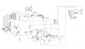
Syncronisationunit:[Bearbeiten | Quelltext bearbeiten]
obsolete
Detects position of the laserbeam
[eagle Dateien im labor-svn]
Better use a impedanceconveter, instead of voltage divieder.
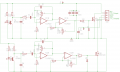
schematics of syncronisationunit
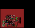
SMD-Board of syncronisationunit


Description
TODO Die LEDs leuchten auf den Spiegel, wodurch das reflektierte Licht auf die Photodioden fällt (nicht kritisch welche), wird differenziert, rauschgefiltert und verstärkt. Am Ausgang des OpAmp schneidet eine Diode die negative Spannung ab. Ist diese groß genug, schaltet der FET (BSS123) durch und zieht die Output Leitung auf Masse. Am anderen Ende der Leitung muss ein Pullup-Widerstand sein, der den Strom auf unter 100mA begrenzt. Versorgungsspannung: 3,7 bis 15 Volt (empfohlen 5 bis 12 Volt).
Syncsensor[Bearbeiten | Quelltext bearbeiten]
Two small IR-LEDs are emitting light onto the spinning mirrors. The deflected light changes the current at the "fototransistor".
Saftyunit[Bearbeiten | Quelltext bearbeiten]
obsolete
The Saftyunit has to detect, that both mirrors are spinning fast enough, to prevent damage to anything in the laserbeam. The saftyunit cuts the laser power as soon as anything shows abnormal behavior.This is a class 3 laser, able to burn wood/paper/flesh even in a few meters distance !
Controlunit[Bearbeiten | Quelltext bearbeiten]
Connected to the controlunit are GLCD, Keyboard, Horizontal-Motor, powersupply, i2C
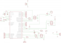
schematics of Controlboard
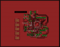
layout of Controlboard


Horizontal mirror[Bearbeiten | Quelltext bearbeiten]
I received a "Laserunit" out of an Epson printer doing 24000 rpm with 7 mirroring sites. 24000*7/60 = 2800 deflections per second.
Connector
Pin Funktion
1 +24V
2 GND
3 Input: 5V TTL 0Khz = 0 U/s, 1 Khz = 400U/s (non-linear scalling)
4 Output: 7*U/sek ??? instable output, from hall, don't use it!
5 ??
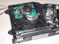
Laserunit of an Epson printer
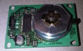
laserprinter mirror front top view label: FL-EGP3901
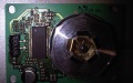
laserprinter mirror back top view Controler: AN44000A label: YG-F1G 36
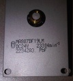
laserprinter mirror back view label: MASQ7DF19LM DC24V 23304min⁻1 2234ZA3 PbF


Lasersupplyunit[Bearbeiten | Quelltext bearbeiten]
This circuit is able to regulate the current going trough the laserdiode. Its able to modulate the beam up to 1Mhz with a 0/3,3V input signal. The output is a rectangle modulated current with an adjustable offset and max. current. An OpAmp is missing in this circuit.
schematic of lasersupplyunit

Imageconversionunit[Bearbeiten | Quelltext bearbeiten]
TODO
Laserdiode[Bearbeiten | Quelltext bearbeiten]
WARNING !
This is a class 3 laser, able to burn wood/paper/flesh even in a few meters distance !
Wear security goggles !
I'm using this laser to project an image at a very big surfaces ! This prevents serious eye damage when looking at the projected point!
Do not look into the beam!
1000mW (1W) Laserdiode 445nm blue 5,6mm
TODO[Bearbeiten | Quelltext bearbeiten]
- Redoing the whole concept
- Design SMD boards
- Buy new motors, mirrors, laser,...
Links[Bearbeiten | Quelltext bearbeiten]
http://elm-chan.org/works/vlp/report_e.html